
Non Destructive Testing (NDT)
Nondestructive testing (N.D.T.) is the process of inspecting, testing, or evaluating materials, components or assemblies for discontinuities, or differences in characteristics without destroying the serviceability of the part or system. In other words, when the inspection or test is completed the part can still be used.
In contrast to N.D.T., other tests are destructive in nature and are therefore done on a limited number of samples ("lot sampling"), rather than on the materials, components or assemblies actually being put into service. These destructive tests are often used to determine the physical properties of materials such as impact resistance, ductility, yield and ultimate tensile strength, fracture toughness and fatigue strength, but discontinuities and differences in material characteristics are more effectively found by NDT.
Non Destructive Test Methods
Test method names often refer to the type of penetrating medium or the equipment used to perform that test. Current NDT methods are:
- Electromagnetic Testing (ET)
- Laser Testing Methods (LM)
- Leak Testing (LT)
- Magnetic Flux Leakage (MFL)
- Liquid Penetrant Testing (PT)
- Magnetic Particle Testing (MT)
- Neutron Radiographic Testing (NR)
- Radiographic Testing (RT)
- Thermal/Infrared Testing (IR)
- Ultrasonic Testing (UT)
- Vibration Analysis (VA)
- Visual Testing (VT)
Magnetic Particle Testing (MT)
Magnetic Particle Testing uses one or more magnetic fields to locate surface and near-surface discontinuities in ferromagnetic materials. The magnetic field can be applied with a permanent magnet or an electromagnet. When using an electromagnet, the field is present only when the current is being applied. When the magnetic field encounters a discontinuity transverse to the direction of the magnetic field, the flux lines produce a magnetic flux leakage field of their own as shown in Figure 1. Because magnetic flux lines don't travel well in air, when very fine colored ferromagnetic particles ("magnetic particles") are applied to the surface of the part the particles will be drawn into the discontinuity, reducing the air gap and producing a visible indication on the surface of the part. The magnetic particles may be a dry powder or suspended in a liquid solution, and they may be colored with a visible dye or a fluorescent dye that fluoresces under an ultraviolet ("black") light.
Liquid Penetrant Testing (PT)
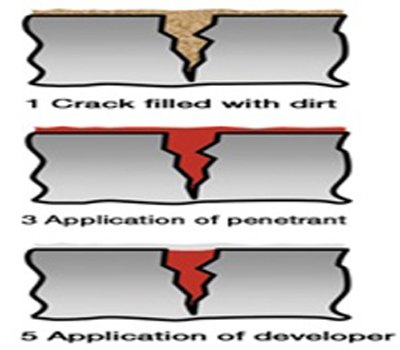
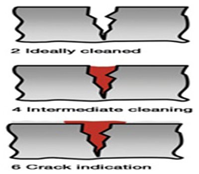
The basic principle of liquid penetrant testing is that when a very low viscosity (highly fluid) liquid (the penetrant) is applied to the surface of a part, it will penetrate into fissures and voids open to the surface. Once the excess penetrant is removed, the penetrant trapped in those voids will flow back out, creating an indication. Penetrant testing can be performed on magnetic and non-magnetic materials, but does not work well on porous materials. Penetrants may be "visible", meaning they can be seen in ambient light, or fluorescent, requiring the use of a "black" light.
The visible dye penetrant process is shown in Figure 7. When performing a PT inspection, it is imperative that the surface being tested is clean and free of any foreign materials or liquids that might block the penetrant from entering voids or fissures open to the surface of the part. After applying the penetrant, it is permitted to sit on the surface for a specified period of time (the "penetrant dwell time"), then the part is carefully cleaned to remove excess penetrant from the surface. When removing the penetrant, the operator must be careful not to remove any penetrant that has flowed into voids. A light coating of developer is then applied to the surface and given time ("developer dwell time") to allow the penetrant from any voids or fissures to seep up into the developer, creating a visible indication. Following the prescribed developer dwell time, the part is inspected visually, with the aid of a black light for fluorescent penetrants. Most developers are fine-grained, white talcum-like powders that provide a color contrast to the penetrant being used.
Radiography Testing (RT)
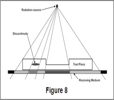
Materials such as aluminum, electrically generated x-radiation (X-rays) are commonly used, and for thicker or denser materials, gamma radiation is generally used. Film radiography uses a film made up of a thin transparent plastic coated with a fine layer of silver bromide on one or both sides of the plastic. When exposed to radiation these crystals undergo a reaction that allows them, when developed, to convert to black metallic silver. That silver is then "fixed" to the plastic during the developing process, and when dried, becomes a finished radiographic film.
Ultrasonic Testing (UT)
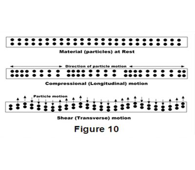
Ultrasonic testing uses the same principle as is used in naval SONAR and fish finders. Ultra-high frequency sound is introduced into the part being inspected and if the sound hits a material with a different acoustic impedance (density and acoustic velocity), some of the sound will reflect back to the sending unit and can be presented on a visual display. By knowing the speed of the sound through the part (the acoustic velocity) and the time required for the sound to return to the sending unit, the distance to the reflector (the indication with the different acoustic impedance) can be determined. The most common sound frequencies used in UT are between 1.0 and 10.0 MHz, which are too high to be heard and do not travel through air. The lower frequencies have greater penetrating power but less sensitivity (the ability to "see" small indications), while the higher frequencies don't penetrate as deeply but can detect smaller indications. The two most commonly used types of sound waves used in industrial inspections are the compression (longitudinal) wave and the shear (transverse) wave, as shown in Figure 10.
Straight Beam Inspection
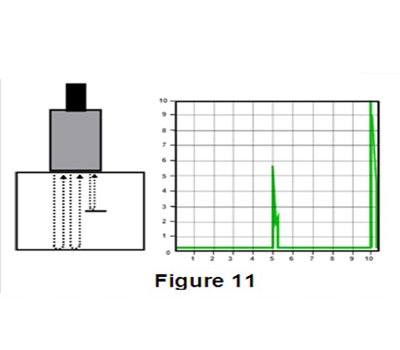
Straight beam inspection uses longitudinal waves to interrogate the test piece. If the sound hits an internal reflector, the sound from that reflector will reflect to the transducer faster than the sound coming back from the back-wall of the part due to the shorter distance from the transducer. This results in a screen display as shown in Figure 11. Digital thickness testers use the same process, but the output is shown as a digital numeric readout rather than a screen presentation.
Angle Beam Inspection
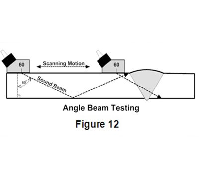
Angle beam inspection uses the same type of transducer but it is mounted on an angled wedge (also called a "probe") that is designed to transmit the sound beam into the part at a known angle. The most commonly used inspection angles are 45°, 60° and 70°, with the angle being calculated up from a line drawn through the thickness of the part (not the part surface). A 60° probe is shown in Figure 12. If the frequency and wedge angle is not specified by the governing code or specification, it is up to the operator to select a combination that will adequately inspect the part being tested. In angle beam inspections, the transducer and wedge combination (also referred to as a "probe") is moved back and forth towards the weld so that the sound beam passes through the full volume of the weld. As with straight beam inspections, reflectors aligned more or less perpendicular to the sound beam will send sound back to the transducer and are displayed on the screen.
Through Transmission Inspection
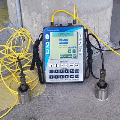
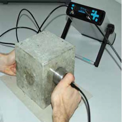
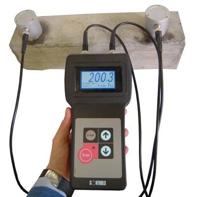
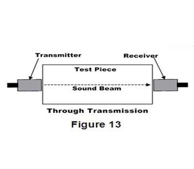
Through transmission inspections are performed using two transducers, one on each side of the part as shown in Figure 13. The transmitting transducer sends sound through the part and the receiving transducer receives the sound. Reflectors in the part will cause a reduction in the amount of sound reaching the receiver so that the screen presentation will show a signal with a lower amplitude (screen height).
Accreditation